Animating Vehicles

by Julian MacDonald (feel free to email comments and suggestions)

Written: September 2002 for Version 1.2


This is a tutorial showing how to animate a car. The main part of the tutorial will focus on making the animation "car.mpg" which involves rotations, setting paths to curves and general use of animation tracks. In addition, other aspects of vehicle animation will be discussed.


Rotations - Quaternion, Euler and Gimbal Lock

The Animation: Car Model

The Animation: Scenery

The Animation: Setting up the Path

The Animation: Getting the Wheels to Spin

The Animation: Headlamps On/Off

Acceleration/Deceleration


Rotations - Quaternion, Euler and Gimbal Lock

Before we start on the animation, we need to understand a few concepts and problem areas with rotations. Although rotating objects sounds straightforward, it's actually quite complex and some apparently odd effects can occur unless you have a proper understanding.

Let's start with an example. Say we want to create a simple axle/wheel arrangement to animate. One obvious way would be to create 2 flattened cylinders for the wheels and one thin, elongated cylinder for the axle and set them up as shown below:


As you can see, the wheels have been parented to the axle so that, wherever the axle goes, the wheels will follow.

OK, now to animate this arrangement. Go to Animate -> Show Score, select the 3 objects and setup their initial positions and relationships (i.e. children follow parents) by setting a keyframe for each position and rotation track at time 0 via Animation -> Keyframe Modified Tracks of Selected Objects. (Most objects normally have position and rotation tracks already assigned - if this is not the case, you need to add one of each to each object via Animation -> Add Track to Selected Objects -> Position/Rotation) .

Now to keyframe the rotation. Move the time marker to 1.0 secs. We're going to spin the wheels through 2 complete revolutions. The obvious thing to do here is rotate the axle through 720 degrees and keyframe. So, try it - select the Axle, go to Object ->Transform Object to bring up the transformation dialogue. We want the axle to rotate around the z-axis, so enter 720 in the relevant box. Now keyframe the new rotation through Animation ->Keyframe Modified Tracks of Selected Objects. Eh ? - no new keyframe appears on the score - what's going on ?

The explanation lies with the way in which the orientation of the object is determined. There are 2 ways of storing orientations: the Quarternion system and the Euler system. The Quarternion system parameterises the actual orientation so that every different orientation has a different and unique 'value'. This is the default system. The problem with quarternions is that they can only represent rotations up to 180 degrees in each axis. That's because, once you go beyond 180 degrees, the orientation of the object is no longer unique. So, in our example, spinning the wheel through 2 complete turns actually ends up with an orientation that is the same as one complete revolution or no revolutions at all - the Quarternion system cannot tell the difference. Because there is no difference, AoI will not allow you to keyframe modified tracks.

The Euler system, on the other hand, stores orientations as combinations of x, y and z rotations. The advantage of this system is that you can specify rotations of more than 180 degrees. So this is what we need in our example. To switch to this mode, double-click the Rotation track of the Axle object to display the track options dialogue. Click the Isotropic (Quarternion) rotations tickbox to switch it off. Now do the transformation again and, this time, when you click on Animation -> Keyframe Tracks of Selected Objects, a keyframe will appear.

However all is not right. Try moving the time marker from 0 to 1 sec; nothing happens ?! OK, let's try deleting the keyframe we set at 1 sec by clicking on it and selecting Animation -> Delete Selected Keyframes. Now, with the time marker at 1 sec again, transform the Axle by 900 degrees (2 and a half revolutions) in the z-axis and keyframe this. Now check the animation again - you should get this:


What is going on ? Well the problem with the Euler rotation system is that when you specify a particular rotation (in this case 900 degrees through the z-axis), the final orientation is not stored in that way. Instead another set of x, y, and z rotations is specified which result in the same orientation. Double-click on the 1 sec keyframe to display the following dialogue:

You can see that, instead of 900 in the z-axis orientation, we have rotations set in all axes. Although this results in the same endpoint orientation, this is no good for animation since the rotations in all the other axes are also being interpolated resulting in a very different movement than that which was intended.

Because rotations are not commutative (i.e. the endpoint depends on the order that the rotations are carried out in) the Euler system always performs rotations in a set particular order: z then x then y. So, if you try and rotate something around the x or z axis, you might not (as in this case) get the result you expect.

So, how do we do it ? The answer is actually quite straightforward. Set up the rotation in the way it will work (i.e. around the y-axis - since this is performed last in the Euler system, you will always get the result you expect) and then parent the top level object (the Axle in this case) to a Null primitive. You can then do what you like in positioning/orientating the Null and, because you're not actually setting up rotation keyframes for the Null itself, everything will behave exactly as it should.

Let's try it. First delete the 1 sec keyframe. Then double-click the 0 sec keyframe to bring up the dialogue and set all axis angles to 0. The wheel system will now turn round and you can see that we now need to rotate around the y-axis to make the wheels spin. So, move the time marker back to 1 sec, and create a keyframe there by selecting the Axle rotation track and using Animation -> Keyframe Selected Tracks. Double-click the keyframe and enter 720 degrees (back to our 2 revs again) in the y-axis. Note that we cannot use the approach we did before (moving to time 1, transforming by 720 degrees and keyframing modified tracks because the results of the transform tool are stored in the quarternion system).

Check the animation now and it should be fine. Now we just need the wheels the right way up. Create a Null object (Object -> Create Primitive -> Null) and position it at the centre of the axle. Now, just delete the keyframe at time 0 for the Axle object - otherwise it will jump to the wrong position later. Drag the Axle and the wheel children in the Object List under the Null so they are children of the Null as below:


Now we simply need to rotate the Null object around so that the wheel system is the right way up. Move the time marker to time 0 first of all - we want to set the position/orientation of the Null from the start. Then rotate the Null object in the normal way (i.e. through the rotate object icon or the transform tool on the object top menu) and Animation -> Keyframe Modified Tracks of Selected Objects .

Phew! - Done it:


So, remember, set up the orientations in the most natural way for the object system and then parent the working system to a Null object so that it can be positioned/orientated in any way you like. Cylinders are naturally aligned so that their long axes are along the y-axis (try drawing a cylinder, then go to Object Layout and ensure all orientation axes are zero -> the cylinder will point along the z-axis)


The Animation: Car Model


The model for the car body is shown below. This is far from being a perfect model but it serves to illustrate the methods in this tutorial.

The wheels of the car are spline tori created by double-clicking the spline tool and changing the Shape to Torus. I chose a fairly thick tyre and, as you can see below, I made them fairly wide as well.


The mudguards were created by making Tubes from curves drawn using the approximating curve tool. The Tubes were converted to triangle meshes which were then flattened as shown below:


The headlights are simply flattened spheres.

The hierarchy of the car model is shown below:


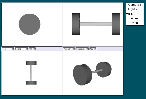
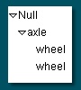
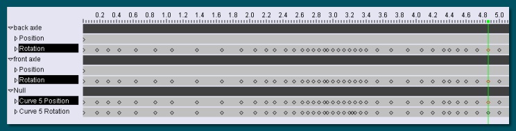
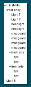
The wheels are parented to their respective axles. The axles here are Null objects and, because of that, the rotations were carried out in a slightly different way to that described above. This is described below.

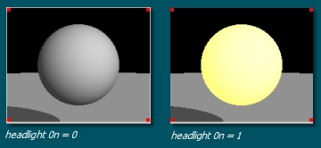
The axles, together with the mudguards and headlights, are parented to the car body and this, in turn, is parented to a Null object. This top level aids things later when we come to animate the car - due to the same principles described in the last section, this Null helps keep the orientation as we want it.

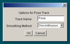
To establish all the proper parenting relations, make sure each object has a Position and Rotation Track, move the time marker to 0, select all objects and choose Animation -> Keyframe Modified Tracks of Selected Objects.


The Animation: Scenery

OK, this is a very simple animation to show a few basic concepts so the scenery is not that exciting !

Basically all we have in the scene is a flattened cube for the ground and a bridge. The bridge was created by drawing a curve of the desired shape in the front view, and then extruding it in first in the z-axis to give the width and then in the y-direction to give it height:


The Animation: Setting up the Path

This is the part where we define the route that the car will take in the animation. This can be done quite elegantly in Art of Illusion by drawing a curve and making the car object follow that curve.

First, draw the curve that the car will follow. In the top view, use the approximating curve tool to draw a loop similar to that shown below left. End the curve by pressing Enter or double-clicking the last point. Now, to make the car go over the bridge, edit the curve by double-clicking the curve in the Object List. This displays the curve editor dialogue. Switch to a view in which you can see a side-on view of the curve and make sure that you can see the bridge by selecting View -> Show -> Entire Scene . Basically all we're going to do is raise the curve so that it follows the shape of the bridge hump. You may need to subdivide the curve (select a number of points and choose Curve -> Subdivide Selection) over the bridge area to give a reasonable number of points to allow you to define the shape correctly. You should end up with something like that below right:


To make the car follow the defined path, select the Null object at the top of the car object hierachy and the curve and click on Animation -> Set Path from Curve . A dialogue similar to that below will be displayed.

Select the appropriate object and curve from the list (in our case there is only one of each).

Make sure the Orientation Follows Curve box is ticked to automatically rotate the car in the right direction as it travels along the curve.

Keyframe Spacing allows you to specify whether the car moves at constant speed or whether it accelerates. Choose Constant Speed for now; acceleration is covered later.

Below this, the dialogue tells us the Curve Length. Make a note of this - we'll need it in the next section.

The next set of entries allow you to specify the speed, acceleration etc. As you enter data in some of the boxes, AoI automatically calculates and updates values in other boxes. In this animation, we want the car to take 5 seconds to get around the circuit so set Start Time to 0 and End Time to 5. The following Speed box is then updated.

Press OK to accept.


This generates new position and rotation tracks entitled Curve 1 Position and Curve 1 Rotation respectively. AoI has calculated the absolute position and rotation values at certain key points. The curves should look something like those below:


Now, make sure that everything moves as it should either by dragging the time marker along and watching the view windows or by using Animation -> Preview Animation. Several things may not be right: The orientation or the height of the car might be wrong. These are easily remedied if you used the hierarchy suggested earlier: move the time marker back to 0 and select the car body object (not the top Null object). Now move the car to the correct height so that it sits on the ground and, if necessary, adjust the orientation so that it faces foward. Then update the keyframes by selecting Animation -> Keyframe Modified Tracks of Selected Objects. Problem solved !

Another problem may be the motion over the bridge. Check this carefully to make sure the wheels contact the bridge as it goes over. If not, the easiest solution is to delete the Curve 1 Position and Rotation tracks, edit the curve as necessary, and then do Set Path from Curve again. You may need to do this a few times before you get it right (I did !).


The Animation: Getting the Wheels to Spin

Now we have the basic motion of the car, we need to make sure the wheels spin correctly. Each spin of the wheel should cause the car to move a distance equal to the perimeter of the wheel which is given by

pi x d

where d is the diameter of the wheel.

Establish the diameter by right clicking on one of the wheels in the Object List and selecting Object Layout. The lowest row gives the sizes of the wheel in each axis; the x or y value (which should be equal) will give the diameter we need. Write this down somewhere.

Now, to create the wheel spin we're going to rotate each axle rather than the tyres themselves. Select the axle objects to display their animation tracks. The first thing we need to do is make sure that the Rotation tracks are set up for the Euler system so that we can animate rotations more that 180 degrees. Double-click each rotation track in turn and turn off the Isotropic (Quaternion) Rotations box.

The next thing is to work out through what angle the wheels turn throughout the whole journey. The number of wheel revolutions is simply equal to the length of the path (which we got from the Set Path from Curve dialogue in the previous section) divided by the perimeter of the wheel

Each revolution is of course 360 degrees, so the total angle is the number of revolutions multiplied by 360.

i.e. angle = 360 x L / (pi x d) where L is the Curve Length.

Move the time marker to the end of the animation (i.e. 5 seconds), select both axle rotation tracks and select Animation -> Keyframe Selected Tracks . This puts a keyframe on the score at that position. Double-click each keyframe in turn and enter the angle calculated above in the Z box. Note that we're using the z-axis here, not the y-axis as discussed above. That's because the torus object is naturally aligned in the z-axis (try drawing a torus and setting its orientation to 0 in all 3 axes via Object Layout - it will point in the z-axis). There is therefore no need to re-align the parent axles objects like we did above.

That should be it. Because we're dealing with constant speed, we only need to set the 2 keyframes. Make sure, though, that the smoothing method for rotation tracks is set to Linear otherwise the wheels may appear to slip.


The Animation: Headlamps On/Off

The last part of the animation is the turning on/off of the headlamps. The headlamp objects themselves are simply flattened spheres with spotlights just in front of them pointing forwards. To make them turn on, we're going to do 2 things: firstly change the intensity of the spotlights from 0 to some other value (depending on the brightness you want - I used 5) to make them project light and, secondly, change the texture of the headlamp spheres from dull grey to a bright yellow to give the impression that they are emitting light.

Let's deal with the spotlights first. We can animate any of the parameters of lights using a Pose track. So select both spotlights and choose Animation -> Add Track to Selected Objects -> Pose. Double-click each pose track in turn to display a dialogue similar to that below:

We want the lights to switch on/off suddenly rather than fade in/out so select Discontinuous for the Smoothing Method.


Now, to set the initial value ('off') for the animation, move the time marker to 0, select both spotlight pose tracks and choose Animation -> Keyframe Selected Tracks to produce a keyframe. Double-click each keyframe in turn to bring up a dialogue as shown below:


You will recognise this as the standard spotlight dialogue but in this case it allows us to set any of the lights parameters at this point in time. Set the desired Cone Angle, Falloff Rate and Color and set the Intensity to 0 to have the light off.

Now move the time marker to the point where you want the headlamps to switch on. Set a keyframe here as before, doube-click it and enter the Intensity as 5 (or whatever). Again, move the time marker to the point in time you want to switch it off again, keyframe and set the Intensity back to 0. The curves for the spotlights should look like this:


Now for the headlamp object texture. To control changes in textures over time, we use Texture Parameter animation tracks. Firstly, we need to set up a texture containing parameters that we can vary with time to give the desired effect. Here's the one I came up with:

The parameter here is called 'headlight on' and it will be equal to 0 when the headlight is off and 1 when it it on.

This parameter is used to switch between 2 simple 'textures'; a plain, dull grey when 'headlight on' equals 0, and a yellow emissive texture when 'headlight on' equals 1.

The parameter is simply used as the scaling factor in 2 colour scale modules (1 indirectly). When 'headlight on' equals 1, the scaling factor for the yellow colour is 1 and the scaling factor for the grey colour (given the by expression 1-headlight on) is 0 and vice versa. The colours are then simply summed using an Add module so that there is a single output to plug into the Diffuse colour property box. The yellow colour is also plugged into the Emissive colour box to give the illusion that light is being emitted.


Assign the texture to the headlamp objects in the normal way.

Now we need to add a Texture Parameter animation track to the Headlamp objects. Select both objects and choose Animation -> Add Track to Selected Objects -> Texture Parameter. Double-click on the Texture track on the score to display the dialogue shown below:

The top part of the dialogue allows the name to be edited and the Smoothing Method to be defined. As with the spotlight, we want the texture to change instantaneously so select Discontinuous.

The lower part of the dialogue lists all the available texture parameters. In our case, there is only one: 'headlight on'. Select this and click OK.

Now, set a keyframe for each headlamp in the Texture track at time 0. Double-click this keyframe to display the dialogue below. Here you can set the value of any parameters selected in the track options previously. In out case, we want to set the value of 'headlight on' to 0.


Now, move the time marker to the place where you want the headlights to come on. Create a keyframe here and edit it to set the value of 'headlight on' to 1. Lastly, move to the point the headlights go off again, set a new keyframe and edit to set 'headlight on' equal to 0 again.


Acceleration/Deceleration


Acceleration and deceleration are obviously an important part of a vehicle's motion and so need to be covered here.

For a basic acceleration/deceleration along a predefined path, this is quite simple to set up. You simply need to draw the path as a curve, select that curve and the Null object at the top of the car object, and select Animation -> Set Path From Curve . Instead of Constant Speed, which we used earlier, this time select Constant Acceleration and enter appropriate values into the time/speed/acceleration boxes. As before, values of some fields are automatically calculated as you enter data in others. Make a note of the initial speed and the acceleration.

That's the car body itself done - now, of course, we need to make the wheels spin correctly. For a straightforward acceleration like this, the most elegant approach here is to use a Procedural Rotation track to calculate the rotation of the wheels at each frame.

Add the track to the axle objects via Animation -> Add Track to Selected Objects -> Rotation (procedural) . The distance, S, that the car has travelled at time, t is given by:

S = ut + 0.5 x a x t2, where u is initial velocity and a is acceleration.

Thus the number of revolutions of the wheels, n = S/(pi x d)

and the total rotation angle, A, = n x 360 degrees.

i.e. A = (ut + 0.5 x a x t2)/(pi x d) x 360 degrees - (1)

Double-click the procedural track on the score list to open the procedure editor. Add an expression module via Insert ->Functions -> Expression and double-click it. Enter equation (1) into the box substituting the appropriate values for S and a which you noted from the Set Path From Curve dialogue earlier. That's it.


For a more complicated motion involving variable acceleration and deceleration along a single track, a different approach is needed (thanks to Peter Eastman for his helpful suggestion here). Start off by drawing the path as before and use the Set Path From Curve tool. Set a constant speed for now. This produces a series of keyframes as we have seen before. Now, select the axle objects and keyframe the end frames corresponding to the curve-car tracks. Double-click the last keyframes and enter the appropriate value for the rotation (= (speed x time)/(pi x d) x 360)). So far, this is the same as we already did in the animation above.

Now create new keyframes for the axle rotation tracks corresponding to the curve-car tracks. AoI should interpolate the rotations at these keyframes correctly - check the score curves to see that the linear relationship is maintained. If not, drag the keyframes to the correct place. If the curve-car position tracks do not have keyframes at all the frames that the curve-car rotation tracks do, then you will also need to keyframe these. Ultimately, you should have matching keyframe positions for curve-car position and rotation tracks and the axle rotation tracks as shown below:


All we need to do now is drag the keyframe around. It is important to drag the keyframes of all the tracks selected above together. For example, to accelerate the car, select the keyframes of all tracks at a particular frame and drag them to the left - because the initial placement of the keyframes represents constant speed, closing up the keyframes accelerates and spacing them further apart decelerates. By keeping the axle keyframes in sync with the car, the wheels are guaranteed to have revolved the correct amount.