Previous: Contents
Next: Setting up the Skeleton

Modelling, Texturing and Animating a Hand

by Julian MacDonald

Modelling the Hand

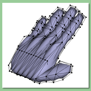
Thinking ahead in the process is important, especially when modelling and animating something complex. In order to create a skeleton for the model, we're going to have to produce a mesh object. But then for something organic, like a hand, this is fine anyway. How to produce the mesh is the next thing to decide. A hand is basically a flat cube (palm) with cylinder-like digits attached to it. One possibility, therefore, might be to create a boolean object out of a cube and 5 cylinders, then convert to a triangle mesh with approximating smoothing as illustrated on the right (for one finger anyway). Note: to get a smooth mesh after conversion, you need to apply approximating smoothing, select all edges and set smoothness to 1.0 (edges are set to smoothness 0 by default).

However, there are problems with the boolean tool and sometimes the joins get a bit messed up when converted to a triangle mesh so this is not my preferred option at present.

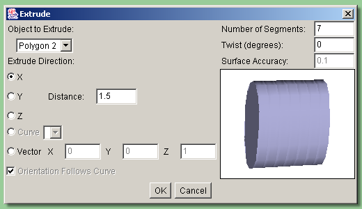
The way that I am going to show you starts with a closed polygon which we're going to extrude into a palm. So, double-click on the polygon tool and enter 4 for the number of sides and 'approximating' for the shape. Now, while pressing ctrl, drag out a rectangle in the left view about twice as high as it is tall. Pressing ctrl produces a 'filled' polygon rather than a curve. You should now get the oval polygon shown to the immediate right. Now select Tools -> Extrude which will bring up a dialogue box similar to that far right. Now, we want to have 4 fingers coming out of the top of the palm and, in between, 3 gaps. So, I have set the number of segments to 7 (this will be clearer later - its all about thinking ahead). I have chosen to extrude in the x direction a distance of 1.5 to give the right proportions for the palm.

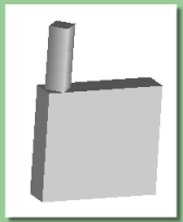
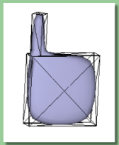
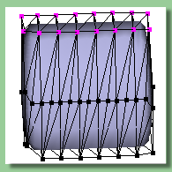
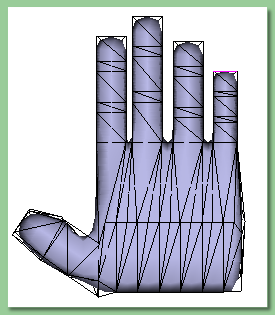
OK, this has created a triangle mesh which can be opened by double-clicking it in the Object List. At the moment, the 'palm' has flat ends which is not very realistic (first image on the right) and the edges between the segments are visible 'ridges'. To solve both these problems, go into EDGE mode and Edit -> Select All then smooth all edges by selecting Mesh -> Set Smoothness and enter 1.0 for this to produce the mesh shown to the far right. This is a bit more like it, though still a long way from looking like a hand.

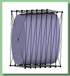
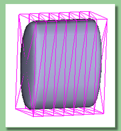
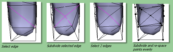
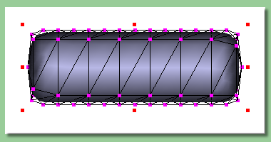
The next thing to do is to create some more points in the body of the palm. At the moment all we have is points at the top and bottom on the palm and this will cause problems when we come to alter its shape. Select all edges and then deselect the top and bottom edges by enabling the select/move tool , holding ctrl and dragging the rectangular selection area first over the top and then over the bottom. Then deselect the end edges by selecting Edit -> Tolerant Selection Mode , orientating the view so that the end can be seen, and control-dragging the selection box over the end edges. With tolerant selecion mode turned on, you don't have to worry about completely enclosing the edge within the selection box. You should end up with the selection shown on the right, i.e. with only the edges streching vertically downwards selected.
Now select Mesh -> Subdivide Selected Edges . This will cause new points be created about halfway down the original edges as shown below left. That will do for subdivision at the moment although we'll need to do a lot more to get a realistic hand - the next thing is to get the digits underway. For the fingers, we're going to extrude faces from the top of the palm. However, following the subdivision, the top is no longer flat - the points at the ends have moved downwards (see middle image below). As extrusion is normal to the face, this may cause a problem so let's get all faces pointing in the same direction. One way to do this is to select all the top points, select Mesh -> Edit Points and enter the same value into the Y box. The actual value is hard to predict - in this case I used 0.8. This produces the mesh shown below right:
Before we extrude the fingers, let's just have a look at the mesh from above by switching the view to TOP. The palm is a bit fat (below left) so select all points, activate the scaling tool and control drag the top handle downwards. The image below right shows the result:
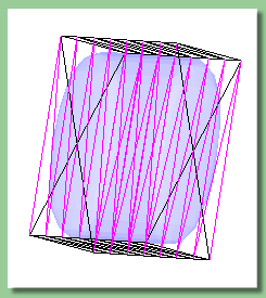
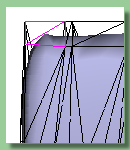
Now a little work on spacing the potential fingers and spaces. Obviously the fingers are wider than the spaces between and at the moment, we have them equally spaced. Select the group of points defining the right-hand base of the first finger and the left-hand base of the second finger. Activate the scaling tool and move the 2 sets of point towards each other by holding ctrl while dragging the side handles. Repeat this for all the spaces to end up with the mesh shown far right.


Right, now we can start forming some fingers. Enter FACE mode and select the 2 faces that form the base of the first finger as shown below left. Now select Mesh -> Bevel/Extrude Faces and enter 0.3 for the height enter 0 for the bevel and apply to 'selection as a whole'. Repeat this for the other fingers to produce the first joint of each finger as shown below middle. Notice that the fingers do not have realistic widths. Selecting the points in each finger and using the scaling tool remedies this as seen below right:


Now for the thumb. Orient the view so that the thumb side can be seen (below left) and select 2 faces that look as though they might form the base of the thumb. As before extrude to 0.3 which should produce something like the second image below. Note that there is a problem where the thumb joins the palm. There needs to be more of a curve. Select the 2 points that define the mesh at that position (3rd image below) and move them down, using the select/move tool, until it looks right. For example below far right:


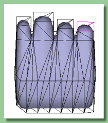
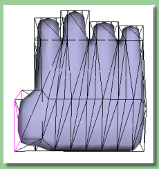
Now to extrude the digits out further. Let's continue with the thumb. Rotate the faces at the end of the thumb joint so that they face upwards using the rotate tool then extrude them a short way (0.1) as before to create some extra points around the joint. Then extrude the new end faces again by 0.4 to create the second thumb segment. Scale the new end of thumb faces to give a realistic tapering as shown on the near right.
Back to the fingers, one by one select the end faces of each finger and extrude a small amount (0.1) for the joints and larger amounts for the finger segments. Eventually you should end up with something like that on the far right.
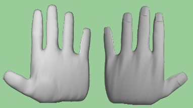
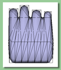
The fingers look a bit straight at the moment so spend some time scaling the joint faces and finger ends to get the right shape. The image on the right shows the hand again following a bit of such tweaking. I have also slightly rotated the fingers outwards to give a more relaxed pose and moved the bases of the fingers up and down to follow a more realistic path.
Let's just do a couple more things to make the hand more realistic. Firstly, we'll try to shape the ball of the thumb. At the moment, there's little we can do as there are not enough points in that area for us to move. To create some more, we go back to the subdivision tool.
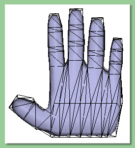
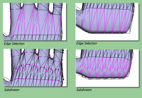
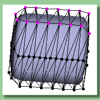
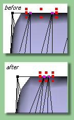
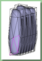
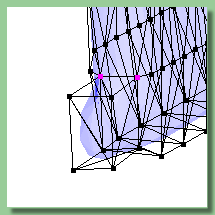
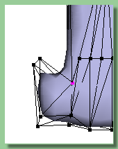
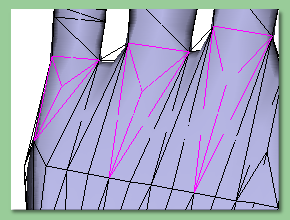
The images on the left show one possible way to do this.

The left hand images show the process for the upper palm. The relevant edges are selected (top) by entering EDGE mode, activating the move/select tool and clicking each edge. The bottom image shows the result of selecting Mesh -> Subdivide Selected Edges.

The same process is then applied to the lower palm shown in the right hand set of images.

This process provides many more points for editing details on the palm which we will now utilise.

To start off, move some of the points to form the curved edge of the ball of the thumb (below left). Ultimately, we're going to raise the faces within this boundary but, if we do this now, the palm above will be stretched outwards too. So, first we'll create some more points inbetween. Select the relevant edges (below middle) and subdivide. Then move the newly created points around the already defined edge of the ball of the thumb (below right). These new points will keep the geometry beyond them the same while we move the ball of the thumb.

Now enter FACE editing mode and select the faces within th ball of the thumb (above left). Use the move outward/inward tool to push the points within the selected area outwards. Use your judgement to give the right bulge (above right).

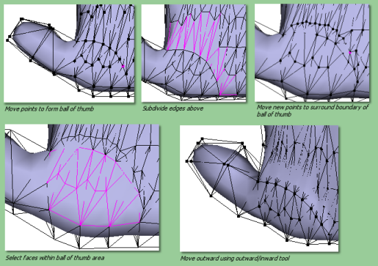
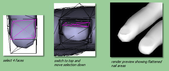
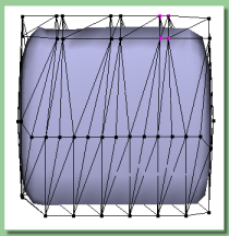
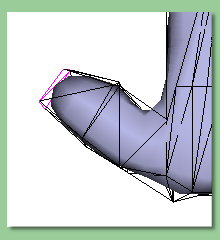
Now for some detail on the back of the hand. We'll start with the knuckles. Orientate the hand to see the back and select the faces where the knuckles ought to be as on the near right image. Subdivide these faces to produce new points at the centres. Select these points and pull them outwards using the move/select tool. Tip - after selecting the points, re-orient to a side view, then drag the points away from then hand. The image below shows the effect. This is quite a simplification and you can obviously take this further to produce more detail but I'll leave it at that for now.
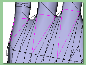

Just to end off, we're going to produce some flattening for the nails. Orient the view to see the end of a finger where the nail ought to be. Select the diagonal edge (below left) and subivide it (next image). Now select the 2 edges shown in the 3rd image below and subdivide again. Rijig the new points to pull them out around the end of the 'nail' (4th image below).


Now select the 4 faces over the nail (below left), alter orientation to see the end-on view and move the faces into the finger slightly (above middle). Repeat this for the other fingers. The image below right is a render preview showing the flattened areas around the nails.

For the nails themselves, I felt it would be easier to make these separately. The nails were formed by drawing a curve like that below left, extruding it once in the z-axis (below middle) to give it thickness and then extruding the result in the y-axis (below right) to give it length. The resulting mesh was edited to give a better shape and then copied 4 times to give 5 nails. The 'nails' were scaled to fit each finger and the boolean tool was used in stages to add the nails to the hand mesh. The final boolean was converted to a triangle mesh.


OK this is the hand at this stage rendered on both sides:


We could go a lot further adding more detail to the hand. It all depends how close-up the final renders are going to be. Bear in mind that a lot of geometry can be simulated with the right textures. We're going to stop there for now and move on the defining a skeleton for the hand


Previous: Contents
Next: Setting up the Skeleton