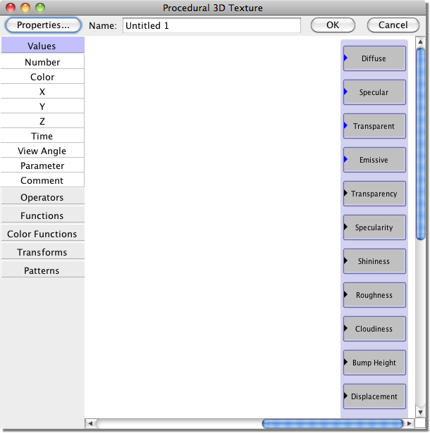
The larger of the two windows displays your procedure, while the smaller one shows a preview of it mapped to a sphere. The sphere should currently be dull white - not a very exciting texture perhaps, but we'll look at ways of making it more interesting in just a moment.
The procedure window should look something like this:
The gray boxes along the right edge of the window represent the standard properties which define the texture. If you have created image-mapped textures before, the names of all the properties should look familiar. You will notice a small triangle next to each name. Those are input ports. Defining a procedure is done by connecting input ports to output ports. We'll see some examples of output ports in just a minute.
You will also notice that some of the input ports are blue, while others are black. The blue ones represent colors, and the black ones represent numbers. Input ports and output ports both come in two varieties, corresponding to numbers and colors. A number input port can only be connected to a number output port, and a color input port can only be connected to a color output port.
Try clicking the mouse on the "Diffuse" input port and holding the button down. (You must click on the triangle itself.) A box will appear next to it with the words "Diffuse (white)". This is telling you that this port corresponds to the diffuse color for the texture (which you already knew), and that its default value is white. Every input port has a default value, which is what it sees when nothing is connected to it. In this case, the default value is white, which is why the texture is solid white. Similarly, if you try clicking on the black input port next to the word "Specularity", you will see that it has a default value of 0, which is why the texture is not shiny.
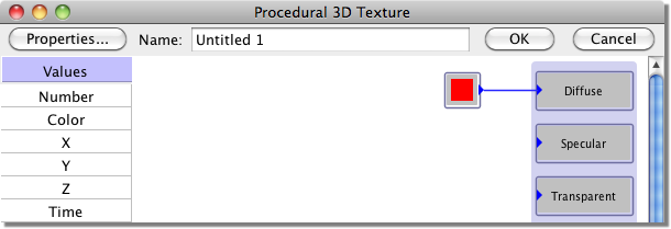
So far, we have lots of input ports but nothing to connect to them. Let's change that. At the left side of the window is a menu of module types that you can add to your procedure. They are grouped into categories like "Values", "Operators", "Functions", and so on. Click on the title of any category to expand it. Initially the "Values" category is expanded, which contains options like "Number", "Color", etc. Click on the word "Color". This will cause a "Color" module to appear in the window. (Alternatively, you can drag from the menu into the main part of the window to create and position the module in one step.)
This is one of the simplest of all modules: it has a single output port which outputs a fixed color. If you double-click on the module, a color picker window will appear to allow you to set the color. Do this, and change the color to be red. When you click OK, the module will turn red.
The color module has a single parameter, which is the color that it outputs. Many (but not all) modules have adjustable parameters. Double-clicking on a module will always bring up a window in which you can adjust its parameters.
Click on the color module's output port. A box will appear next to it containing the word "Color". This is simply to tell you what this output port corresponds to. In this case, it is obvious, but for modules with multiple output (or input) ports, these messages are very useful.
Still holding the mouse button down (so that the text box is visible), drag the mouse around the screen. A black line will stretch from the output port to follow the mouse. This is how you create links between ports. Move the mouse over the "Diffuse" input port. When the mouse is correctly positioned, a second text box will appear next to the input port. Finally, release the mouse button. The line should remain, connecting the input and output ports, and the sphere in the preview window should turn red. The procedure should now look something like this:
Now click on the word "Number" in the menu at the left side of the window. This will create a "Number" module, which is analogous to a color module, except that it outputs a number instead of a color. Double-click the number module, set its value to 0.2, and click OK. Notice that the module changes to display the value you entered.
Click on the number module itself (not on its output port), and drag it around the screen. You can drag modules to position them wherever they are most convenient. Place it close to the "Specularity" input port, and drag a link between the number module and the specularity port. The sphere in the preview window should become shiny. Every time you make a change to the procedure, the preview window is immediately updated.
This is all very well, but it isn't much of a procedural texture. In fact, you could easily have created the exact same thing as a Uniform texture. Now let's try something more impressive.
First, click on the color module. A red outline will appear around the module to show that it is selected. Press the delete or backspace key on your keyboard to delete it. Now delete the number module in the same way. The preview should be dull white again.
Now create two new modules. Click on the "Color Functions" category to expand it and create a "Blend" module. Then expand the "Patterns" category and create a "Marble" module. Hook them up like this:
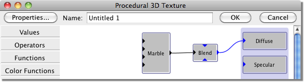
The preview should now look like this:
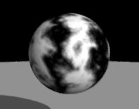
That's a bit more impressive - and it only required two modules!
Try clicking on the various input and output ports of these modules. You will see that the Marble module has inputs corresponding to the X, Y, and Z coordinates of a point in space, and outputs a single value. This module defines a function which mimics the veins and swirls found in marble. To convert this numeric function into a color, we use a Blend module. This module has three input ports: two colors and a number. It uses the number to interpolate between the two colors. The color inputs have default values of black and white, respectively, which is why the texture appears black and white. You can easily change this, however. Simply create a color module, set its color, and then connect it to either of the Blend module's color inputs. Of course, you aren't limited to connecting color modules to these inputs. Any color output can be connected to them - which might itself be a complex pattern generated by a series of modules.
An input port can only have a single output port connected to it. It would make no sense otherwise. On the other hand, a single output port can be connected to any number of input ports. Suppose, for example, that you want the white stripes of the marble to be reflective, but not the black ones. Simply drag a link between the output of the Marble module and the "Specularity" input. Presto!
Just as you can click on a module to select it, you can also click on a link. Select the link you just drew (if it is not already selected), and press the delete or backspace key. The link will disappear, and the texture will return to its previous appearance.
You now know all the important concepts for creating procedures. All that's left is the hard part: actually getting to know all the different modules available for your use. There are more than 50 of them, and they offer sufficient power and flexibility to create a nearly unlimited assortment of procedural textures and materials. They are described in detail in the following chapters, but if you start to feel overwhelmed by the amount of information, relax and just start playing with them. This is the best way to learn about the various modules, and along the way you are bound to discover some interesting textures!