1. Art of Illusion Basics
1.1. Overview
Art of Illusion (AoI) is a program for creating high quality, photorealistic (or non-photorealistic) still images and animations (either in .mov format or as a sequence of still frames which can be joined together using other software to make movie files). Images are produced by rendering scene files. These scene files need to contain some 3-D objects, at least one light (or some form of global illumination) so that the objects can be seen and at least one camera, the view from which provides the image. Complex scenes may contain many hundreds of objects and several lights. Files built for animation may have several cameras between which the view is cut to make for an interesting animation sequence.
3-D objects come in 4 basic flavours: Primitives, spline meshes, triangle meshes and tubes, all of which are described in detail later in this manual. Art of Illusion has highly flexible, but easy to use, editors for textures (surface properties such as colour, bumpiness, shininess, transparency etc.) and materials (inner properties for simulating glass, smoke etc.).
Animation of objects within the scene is achieved with a keyframing system including support for skeletons using forward and inverse kinematic animation. Textures can also be animated.
Rendering of the scene file is achieved with a fast raster engine or a high quality raytracer capable of producing photorealistic images. Motion blur, depth of field, Global Illumination and caustic effects are supported.
In addition, Art of Illusion includes a scripting feature allowing the creation of new types of objects and tools amongst virtually unlimited other possibilities via the Beanshell scripting language.
Plugins and scripts are also available that allow additional objects and tools - see the Scripts and Plugin Manager for details of how to find and install these. This manual only details the basic AoI program - please refer to developers documentation for their own scripts and plugins.
A good place to start, unless you want to read the whole manual first, are the tutorials located at the Art of Illusion web site (www.artofillusion.org). The hourglass tutorial gives an excellent introduction to using the program and useful details on the texture/material support and meshes are also available in other tutorials.
1.2. Getting Started
1.2.1. Main Screen Layout
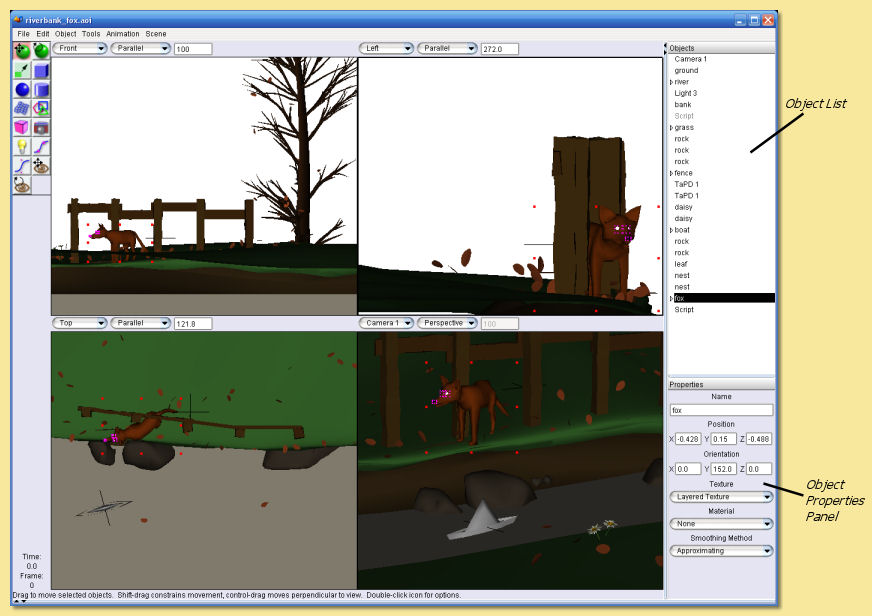
The screenshot below shows the main window:
Note that since version 1.8, Art of Illusion uses a UI based on Java Swing. This means that the ‘Look and Feel’ of the interface can be customised to a certain extent. (see the scripting chapter for details). Also, since version 2.5, plugins can alter the display, icons etc.
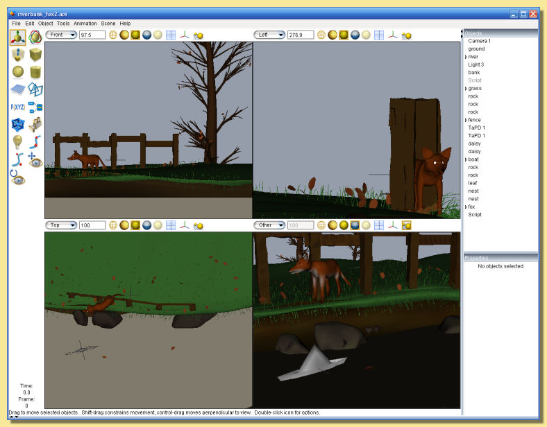
See the DisplayModelIcons and ElectricWaxTheme downloadable through the Scripts and Plugins Manager - these plugins will transform the above into a display like this:
The main window is divided into several area: the 4 interactive view windows, the Object List and the Object Properties Panel, and the tool icons, each of which are described in detail below. The animation score can also be displayed - see the animation section for details. The side panels are dockable so that the display can be configured as required - simply drag the top bar of the Object List, the Properties Panel or the Score to move the panel to the top, bottom or sides of the display.
1.2.2. View Windows
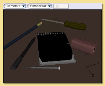
The 4 windows in the main part of the screen show different views of the scene. By default, the two upper windows and the lower left window show parallel or orthogonal views of the front, side and top respectively and the lower right window shows a perspective view from the currently-selected camera. These views can be easily altered using the drop-down menus at the top of each view window.
The window with ‘focus’ or the selected window is the one with the thicker outline (the upper left window in the example
screenshot above). This is relevant for any operations that work on single view windows. To change the selected window,
simply move the cursor to the required window and click. All view windows can be panned, zoomed and rotated
independently using the camera controls: 
Zoom/Magnification Controls:
Select Move mode by clicking on
 then hold down CTRL while dragging the right mouse button up
(zoom out) or down (zoom in) or
then hold down CTRL while dragging the right mouse button up
(zoom out) or down (zoom in) orUse the scroll wheel - scrolling down zooms in and scrolling up zooms out. Holding down ALT while using the scroll wheel zooms in/out faster.
For a more detailed discussion of the various view options, and advanced ways of moving your viewpoint around the scene, please see The Viewpoint Management Chapter.
If you find it easier to work with one large window, select Scene -> One View from the top menu bar and the currently selected window will fill the workspace.
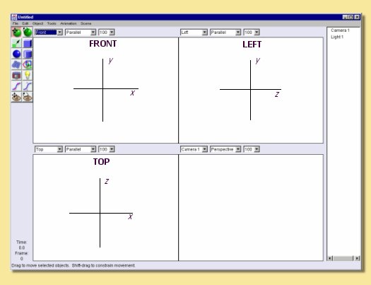
One other thing that you need to know is the orientation of the coordinate system used, as this varies between 3D programs. Art of Illusion uses a right-handed coordinate system - when the positive x-axis points right and the positive y-axis points up, the positive z-axis points out of the monitor. If you are facing front, the y-axis is up and down, x is left and right and z is forward and backward. The axes for the default viewports are thus as follows:
Sometimes it is useful to be able to quickly visualise the whole scene or a selected object within the view windows. This is achieved through Scene -> Frame Selection with Camera, which adjusts the zoom and centering of the non-camera view windows so that the selected objects just fit within them, and Scene -> Frame Scene with Camera which similarly fits the whole scene into the windows.
1.2.3. Display Mode
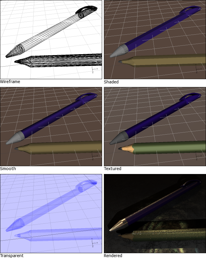
There are 6 possible ways in which to view the scene in real time: Wireframe preview, Shaded preview, Smooth preview, Textured preview, Transparent preview, and Rendered preview. The type of preview is selected from the top menu bar Scene -> Display Mode -> Wireframe/Shaded/Smooth/Textured/Transparent/Rendered and affects the view window with ‘focus’. The difference between them is shown in the figure below:
The choice of preview mode affects performance of real time camera movements with speed potentially decreasing from Wireframe -> Shaded -> Smooth -> Textured -> Rendered. Depending on the specifications of the computer being used, this will be more noticeable on complex scenes. The preview type can be set independently for each view window.
Note that Shaded and Smooth previews show colours which match, albeit in a simplistic way, the textures assigned to each object. The Textured preview gives a closer representation of the actual textures, and Rendered preview shows exactly what the objects will really look like. See textures_and_materials for more detail.
1.2.4. Icons
At the upper left of the screen are the icons for quick selection of common tools. They allow you create new objects and to move, rotate and scale existing objects. Resting the cursor over the icons will bring up a tooltip to describe its function.
The image on the right gives a brief description of each icon and the tools themselves are explained in more detail in relevant sections of this manual.
For each tool used, there is a line of text at the bottom of the screen which briefly describes its use.
With the Move tool and Rotate tool, objects can be moved one pixel at a time with the keyboard arrow keys and 10 pixels at a time when the ALT key is used with the arrow keys.
The Move/Scale/Rotate tool provides a collection of controls for moving, scaling, and rotating the selected objects without needing to change tools. It is described in detail in the section on editing meshes.
The Spacebar can be used to quickly switch between tools; pressing it will toggle selection between the default tool (either Move or Move/Scale/Rotate, depending on your preference settings) and the last tool used.
1.2.5 Object List and Properties Panel
Finally, on the right hand side of the main screen are the Object List (at the top bu default) and Object Properties Panel (at the bottom by default).
Not surprisingly, the Object List is a list of all the objects, including cameras and lights, in the scene. Objects can be selected from this list for editing simply by clicking on them. To select more than one object, hold down the key while clicking or, to select a range, click on an object and click on another to select all the objects in between.
Some types of object (e.g. curves, splines and meshes) allow editing additional to the standard move, scale and rotate. Double-clicking on objects in the Object List opens up the relevant editing tool (see editing_objects).
This list also allows the hierarchical arrangement of objects so that a number of objects can be ‘children’ of other objects. Moving, scaling and rotating ‘parent’ objects can result in the children objects also being transformed depending on the tool setting (see Transforming Objects). An object can be made a child of another object by clicking on it and dragging it underneath the intended parent. An arrowed bar shows the position of the object in the list. Indentation of this bar indicates that the object can become a child of the object above it in the list. Releasing the mouse button causes this to happen and the parent object then has a down arrow displayed next to it to indicate this hierarchy. Clicking on this arrow hides the children and the arrow changes to a right pointing arrow.
Arranging a parent-child hierarchy between objects can also be useful during animation.
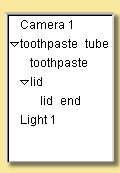
In the example on the left, the object hierarchy for a toothpaste tube scene is given. In this case, ‘toothpaste’ and ‘lid’ are children of ‘toothpaste tube’ and ‘lid end’ is a child of ‘lid’. Transformations made to ‘toothpaste tube’ can be set so as to affect all the objects mentioned, whereas those applied to ‘lid’ can affect only ‘lid’ and ‘lid end’.
If required, the Object List can be hidden from view by selecting Scene -> Hide Object List.
Right-clicking on objects in the Object List displays a menu of operations available for that object including various editing tools, application of texture and materials and the ability to hide/show that object. The options are also available via a context menu which can be brought up by right clicking objects directly in the view windows.
The Object Properties Panel shows the various editable properties for the currently selected objects as shown in the example below.
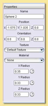
The properties that appear in this pane depend on the type of object(s) selected. In this example, the properties for a sphere object are displayed and can be edited.
The Position and Orientation values can be entered directly and the texture and material can be set.
The X, Y and Z radii of the object can also be set directly in the relevant text fields or can be altered via the control knobs to the right of each. To operate these, move the cursor over the knob and hold down the left mouse button while dragging left or right. To effect larger changes in value, the ALT key can be depressed while dragging.
1.2.5. Hiding/Showing Objects
It is sometimes useful to be able to hide objects from view, for example in a complicated scene where some objects overlay those you wish to work on. To hide objects, select them and click on Object -> Hide Selection. Alternatively right click the selection in the Object List or the object itself in one of the view windows and choose Hide Selection. This will also hide them in the rendered image which is useful when you just want to test the rendering of certain objects. Hidden objects are shown as grey in the Object List.
To show objects again, select them and click on Object -> Show Selection or right click the object(s) in the Object List or in the view windows and select Show Selection.
1.2.6. Locking/Unlocking Objects
Another useful tool when you want to work on just a few objects is to lock other objects. When an object is locked, all clicks on it in the view are ignored. It is still visible (unlike when you hide it), but in all other ways it behaves as if it were not there. To hide objects, select them and click on Object -> Lock Selection. Alternatively right click the selection in the Object List or the object itself in one of the view windows and choose Lock Selection.
To unlock objects again, select them in the Object List (because of course you can’t select them in the view) and click on Object -> Unlock Selection or right click the object(s) in the Object List and select Unlock Selection.
1.2.7. Grids
It is often helpful to be able to position objects accurately and switching on the grid will aid this. The grid is activated via Scene -> Grids which brings up the following dialogue box:
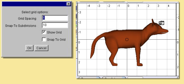
The grid spacing determines the spacing between the lines of the grid seen in each window. To actually see the grid, you need to tick the Show Grid box. It is also possible to activate a Snap to Grid mode which forces objects to be positioned at discrete locations rather than allowing complete freedom of movement. Tick the Snap to Grid box to enable this and enter the relevant number of Snap-to Subdivisions. This is the number of uniformly distributed allowable positions within each grid square. So, the higher this number, the more freedom of movement there is. In the example on the left, objects will snap to every 1/10 of the grid spacing if the Snap to Grid box is ticked.
Switching on the grid will display the grid on all view windows. In addition, perspective views will display a ground plane.
1.2.8. Coordinate Axes
When navigating around the scene, it is sometimes possible lose track of your orientation. To aid you in this situation, you can turn on Coordinate Axes via Scene -> Show Coordinate Axes. This displays 3 lines labelled x,y and z representing the axes as seen below:
If desired, the coordinates axes can be turned off via Scene -> Hide Coordinate Axes.
1.2.9. File Menu
The leftmost item on the top menu bar, File allows various file operations to be performed. Clicking on this will bring up the File menu as shown below:
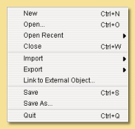
New opens up a new instance of Art of Illusion for creating a new scene. This blank scene contains by default a camera and a directional light.
Open opens up an existing Art of Illusion scene file in a separate instance of AoI.
Open Recent shows a list of the last 10 scenes that were opened and lets you select one to open.
Close closes the current scene file. If this is the only instance of AoI open, then it will exit completely from AoI.
Import allows 3D models in formats other than AoI to be opened. The only supported file format is wavefront .OBJ and the importer also allows OBJ materials to be imported. Simply select the OBJ file when prompted and the material file will be automatically read and converted to an AoI texture. The model will automatically be scaled on import to better fit AoI scale units.
Export AoI can save 3D models/scenes in 3D formats other than AoI. Export can be made to either Wavefront OBJ, VRML or Povray v3.5 files including partial support for textures. You can select whether to export the whole scene or just the selected object and can specify the maximum surface error in the appropriate dialogue shown below. A lower value for the error will result in a more complex and, therefore, larger export file.
OBJ and VRML exported 2D textures are saved as image maps of the size and quality specified in the relevant dialogues.
There are additional options for VRML and Povray as shown in the dialogues below:
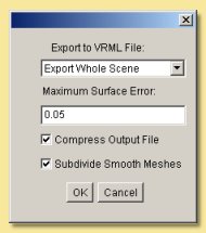
VRML export option dialogue
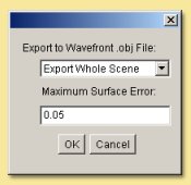
OBJ export option dialogue
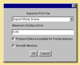
Povray export option dialogue
Link to External Object
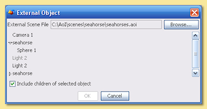
This is a way of using an object from another AoI file in the current scene via a dynamic link to that file. Using this method, changes made to the source object automatically affect any files which have links to that object. This allows, for example, a character model to be created and kept in one file which can then be used in many other scenes - modifcations to the character can then be made to the original file which will then be applied automatically to any scene files that have the link.
Selecting this option displays a dialogue, an example of which is shown on the right. This allows the selection of the source file and the object within that file that is to be linked to. You can choose the include the children of the selected object as well.
Save saves the current file with the existing name or will prompt for a new name if the file has not been saved previously. A ‘safe save’ method is used which ensures that the file is saved properly before the existing file is overwritten.
Save As allows the file to be saved with a different name.
Quit closes down all currently open AoI files and shuts down AoI completely. You will be prompted to save any of the files that have not yet been saved.
1.2.10. Edit Menu
The Edit menu on the top menu bar contains some very useful selection and basic object manipulatiom tools.
The menu looks like this:
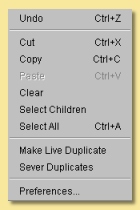
Undo/Redo undoes the last action or redoes the last undo, including selections.
Cut makes a copy of any currently selected objects in memory while deleting the originals.
Copy is like Cut but the original objects are retained.
Paste creates as new objects any that have been put in memory by Cut or Copy tools.
Clear deletes all currently selected objects.
Select Children selects all objects that are ‘children’ of currently selected objects.
Select All selects all the objects in the scene.
Make Live Duplicate makes a special copy of any currently selected object in that they are dynamically linked so that any changes made to one are automatically made to all other live duplicates. Note that this method of copying uses significantly less memory than making several normal copies via the copy/cut/paste tools.
Sever Duplicates ceases the association between live duplicates so that they become independent objects
Preferences allows various general parameters to be set up for future instances of AoI. (This item appears in the Edit menu on Windows and Linux, but in the application menu on Mac OS X.) Selecting this option produces the following dialogue:
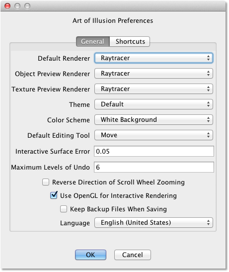
There are 2 tabs for preferences: General and Shortcuts. The preferences under the General tab are described below:
The Default Renderer defines the default rendering engine used for rendering scenes.
The Object Preview Renderer defines the default renderer used when carrying out render previews in the spline mesh and triangle mesh object editors.
The Texture Preview Renderer defines the default renderer used in the various texture dialogues.
The Theme defines the overall appearance of windows in AoI. A single default theme is included with the program. Others can be downloaded with the Scripts and Plugins Manager. Each theme provides a selection of Color Schemes to choose from.
The Default Editing Tool is the tool that should be selected in a window when it first appears. You can also press the spacebar in a window to quickly toggle between the default tool and another selected tool.
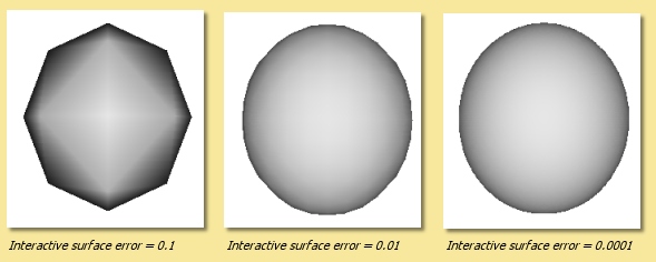
The Interactive Surface Error defines the surface accuracy of objects displayed in the main window and the object editors. The lower the value, the more acccurate the surface displayed is as shown below. Bear in mind, however, that a low surface error will result in a poorer performance in terms of speed.
Maximum Levels of Undo defines how many of the last operations are stored by AoI and hence how many can be undone. The greater this number is, the more steps can be undone, but the greater the memory requirement.
Reverse Direction of Scroll Wheel Zooming lets you control how zooming with the scroll wheel works. By default, scrolling up zooms in. Selecting this option reverses that.
Use OpenGL for Interactive Rendering By default, Art of Illusion uses OpenGL, through the JOGL libraries, to speed up the interactive displays in the main window and object editors. If there are problems with this, the option can be switched off here to allow software rendering.
Keep Backup Files When Saving creates a backup of the last saved file when the file is saved with the same name. The backup file has the additional extension .bak.
Lastly, the Language defines which language all the dialogues will be shown in. As of version 2.0, you can choose from Danish, English(United States), French, German, Italian, Japanese, Portuguese, Spanish or Swedish.
The
Shortcuts tab of the preferences dialogue is shown below. This dialogue allows keyboard shortcuts, additional to those described in section 1.2.12, to be set up. The keys defined trigger scripts to carry out particular tasks. New shortcuts can be added or existing ones can be edited. This allows Beanshell scripts to be written in a special dialogue to carry out the series of commands required.
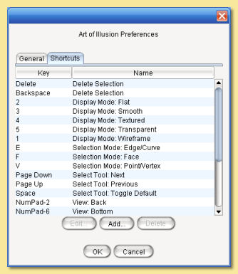
The default shortcuts are:
Backspace |
Delete Selection |
Delete |
Delete Selection |
1 |
Display Mode: Wireframe |
2 |
Display Mode: Flat |
3 |
Display Mode: Smooth |
4 |
Display Mode: Textured |
5 |
Display Mode: Transparent |
E |
Selection Mode: Edge/Curve |
F |
Selection Mode: Face |
V |
Selection Mode: Point/Vertex |
Page Down |
Select Tool: Next |
Page Up |
Select Tool: Previous |
Space |
Select Tool: Toggle Default |
NumPad-0 |
View: Toggle Perspective |
NumPad-1 |
View: Front |
NumPad-2 |
View: Back |
NumPad-3 |
View: Left |
NumPad-4 |
View: Right |
NumPad-5 |
View: Top |
NumPad-6 |
View: Bottom |
NumPad-7 |
View: Camera 1 |
NumPad-8 |
View: Camera 2 |
NumPad + |
View: Zoom In |
NumPad - |
View: Zoom Out |
1.2.11. Using Template Images
Art of Illusion allows the background of the view windows to be set to an image. This is useful when modelling objects that benefit from a reference image. To select an image to assign to the background, click in the view window you want the template image to be displayed and then select Scene -> Set Template Image. This brings up a dialogue allowing the choice of an image in either .jpg, .gif or .png format. After selecting the image, it will be displayed as the background of the selected view window.
To hide the image, select Scene -> Hide Template and to show it again select Scene -> Show Template . These actions can also be carried out to hide/show template images in the spline and triangle mesh editors.
1.2.12. Keyboard Shortcuts
To speed up workflow, many of the tools and functions have hard-coded keyboard shortcuts. These are summarised below:
File Functions:
Ctrl+N |
Create a new AoI file |
Ctrl+O |
Open an existing AoI file |
Ctrl+W |
Close the current AoI file |
Ctrl+S |
Save the current AoI file with the same name |
Ctrl+Q |
Quit Art of Illusion |
Edit Functions:
Crtl+Z |
Undo/Redo last action |
Ctrl+X |
Cut the selected object(s) to the clipboard |
Ctrl+C |
Copy the selected object(s) to the clipboard |
Ctrl+V |
Paste the object(s) from the clipboard into the file |
Ctrl+A |
Select all the objects in the scene |
Delete |
Clear selected object(s) |
Object Functions:
Ctrl+E |
Edit Object |
Ctrl+L |
Edit the object layout |
Ctrl+T |
Open the Transform Object Dialogue |
Ctrl+U |
Set Texture for currently selected object(s) |
Ctrl+M |
Set Material for currently selected object(s) |
Arrow keys can be used to move/rotate selected object(s) in the plane of the currently selected view window if the Move/Rotate Icons are on. Holding Ctrl while pressing the up/down keys moves/rotates in the other axis. Holding ALT while pressing the arrow keys moves/rotates the object by 10 pixels.
Animation Functions:
Ctrl+P |
Preview Animation |
Ctrl+] |
Move forward one frame |
Ctrl+[ |
Move backward one frame |
Ctrl+J |
Jump to time … |
Ctrl+D |
Edit selected keyframe |
Ctrl+K |
Keyframe selected track(s) |
Ctrl+Shift+K |
Keyframe modified tracks |
Ctrl+Shift+A |
Select all tracks of selected objects |
Scene Functions:
Ctrl+R |
Open the Render dialogue window |
Ctrl+Shift+R |
Render immediately with current settings |
Ctrl+B |
Toggle between one view mode and four view mode |
Ctrl+G |
Open Grid dialogue window |
Ctrl+F |
Frame selection with camera |
Ctrl+Shift+F |
Frame scene with camera |
Ctrl+Shift+U |
Open Textures dialogue window |
Ctrl+Shift+M |
Open Materials dialogue window |
Mesh Editor Functions:
Ctrl+Z |
Undo/redo last action |
Ctrl+A |
Select all vertices/edges/faces |
Ctrl+X |
Extend selection |
Ctrl+F |
Toggle freehand selection mode |
Ctrl+W |
Display as quads |
Ctrl+M |
Open Mesh Tension dialogue |
Ctrl+E |
Edit selected point(s) |
Ctrl+T |
Transform selected point(s) |
Ctrl+B |
Bevel/Extrude selection |
Ctrl+P |
Open texture parameters dialogue |
Ctrl+S |
Set smoothness for selected vertices/edges |
Ctrl+R |
Render preview |
Ctrl+D |
Open Edit Bone dialogue |
Ctrl+G |
Open Grid dialogue |
Arrow keys can be used to move selected points one pixel at a time in the plane of the view if the Move Icon is selected. Holding Ctrl while pressing the up/down keys moves in the other axis. Holding ALT while pressing the arrow keys moves the points by 10 pixels.
There is also the ability to set up additional keyboard shortcuts via Edit -> Preferences -> Shortcuts tab.