13. Viewpoint Mangement
While working on your 3D scene or model, you will probably want to move the view around to look at things from multiple perspectives. You may also want to move a camera to properly frame a scene for rendering.
This section explains the tools available, and the 4 modes that affect their operation.
13.1. Basic View Controls
The view can be rotated by using the  tool. It can be moved
by using the
tool. It can be moved
by using the  tool. Both of these tools are affected by the
rotation mode of the current view, discussed in greater detail below.
tool. Both of these tools are affected by the
rotation mode of the current view, discussed in greater detail below.
View Zoom/Z-depth is controled primarily via the scrollwheel. It is also affected by the mode. If your mouse does not have a scrollwheel, you can use Ctrl + Right Drag.
For more advanced users: when you really get into the modeling flow, you probably don’t want to keep changing tools just to move the camera. All view control functions are accessible through mouse + hotkeys, explained in more detail below.
Each view has several attached widgets that control and display the status of the view:

13.1.1. Preset View Targets
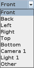
These are defined view locations and orientations that can be accessed directly by clicking on them in the menu. The six cardinal directions (Top, Bottom, Left, Right, Front & Back) are fairly self-explanitory, but the other targets deserve a little explanation:
- Other
This is simply a status marker to indicate that you are not currently using one of the preset targets. It usually means that you started at one of the cardinal directions, and then moved the view.
This option is generally not something you would select from the list
- Camera 1(2, 3, &tc, &tc..)
View the scene through the specified camera.
If you use the view pan and rotate controls while viewing through a camera, you actually move the camera! This is very handy for framing a scene for rendering stills, or for setting up keyframes for position and rotation tracks for the camera.
Note
When viewing through a camera, the Projection is locked to Perspective.
Unlike other targets, the Field of View is managed by the specific camera
- Light 1
This is not a bug or mistake! You can view the scene from the perspective of Directional Lights and Spot Lights.
Why would you want to?
Experience has shown us that it can be very tricky to properly align such lights from an independent viewpoint. Much like the cameras, moving the view while using a light as a target moves the light.
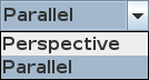
13.1.2. Projection Type
|
Parallel Orthographic Projection. All distances are represented at the same scale, regardless of depth in the scene. No foreshortening effects. This is how a scene would be represented for plotting in technical drawings. In this example, all three primitives are the same size: 1 unit in each dimension. Note In this projection, the zoom field represents scale in pixels per scene unit |
|
Perspective More visually realistic projection, including foreshortening effects. This represents the scene as seen by an actual observer. When viewing the scene through a camera, the camera’s Field Of View is used. From other viewpoints, a generic set of camera specifications is used. Note In this projection, the zoom field represents the distance, in scene units, to the viewpoint rotation center. |
13.2. Advanced View Settings
This section discusses Hotkey/Mouse shortcuts for a more ergonomic workflow, as well as the four view control Modes that fine-tune the control experience.
13.2.1. Mouse Combinations
All view movements can be accessed through a standard mouse. A three button mouse works best, but there are key combos that support a one or two button mouse. (As long as your window manager does not trap the hotkey!) The supported key combos are as follows:
- Right Button
Meta + Primary mouse button (most common on OSX)
- Middle Button
Alt + Primary mouse button
- Scroll Wheel
Ctrl + Right Drag (up and down)
We’ve tried to make the combinations as smooth and intuitive as possible - just try them. You might never go back to the view tools!
Mouse Action |
Tray Mode |
Space Mode |
Fly Mode |
Drive Mode |
|---|---|---|---|---|
Center Click in view |
Center view on click location. Set working depth to surface of nearest object. If no object at this location, keep current working depth. |
|||
Center Click in Object List |
Fit object to active view. Set working depth to center of object. |
|||
Center Drag |
Rotate around screen center at working depth |
Rotate around current view location (pan) |
||
Ctrl Center Drag |
Tilt View around Z-axis (Barrel Roll) |
|||
Ctrl + Shift Center Drag |
Rotate around current view location (pan) |
Rotate around screen center at working depth |
||
Right Drag |
Move View in Screen space - Left, Right, Up, Down |
|||
Scroll Wheel |
Move closer/further from the rotation center. |
Move along view axis (See Scroll-Cues for some of the fine points) |
||
Alt Scroll |
Precision Z-movement (Slower) |
|||
13.2.2. Modes
These modes affect how the camera responds to rotate, move, and zoom commands.
13.2.2.1. Why so many ways to move a camera?
Some tasks in AOI lend themselves to different camera control approaches. Broadly, there are two basic types of camera activity:
- Modeling
Focuses on a specific object, or part of the object. You may need to get a different view, but the object should stay in the center of the view.
The Tray and Space modes are designed to service this use case.
- Travel
Focuses on the movement of the camera through the scene, such as setting a camera path for an animation sequence.
The Fly and Drive modes are designed for this, as they mimic real-life camera dollys
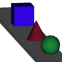
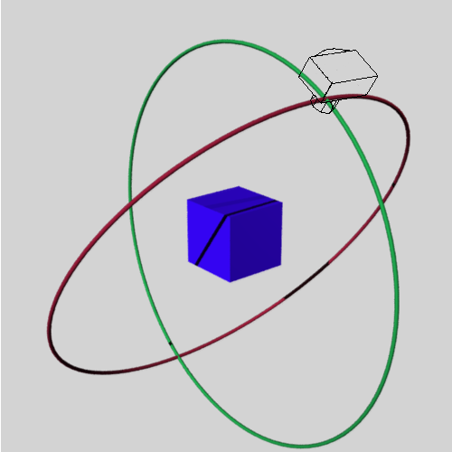
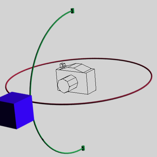
13.2.2.2. Tray or Turntable
This is the default control mode. The viewpoint rotates around a point in space. You can pick the rotation point using center-click in either the view or the object list (See the mouse control table)
Zoom or Z-axis movement moves the view closer to or further away from the rotation point. It does not move the rotation point, nor can you zoom in past the rotation point.
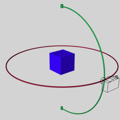
In these images, the blue cube has been selected as the rotation point:
|
The green and red pipes represent the paths that the viewpoint will follow if the view is rotated |
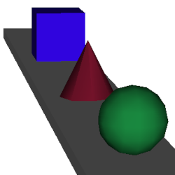
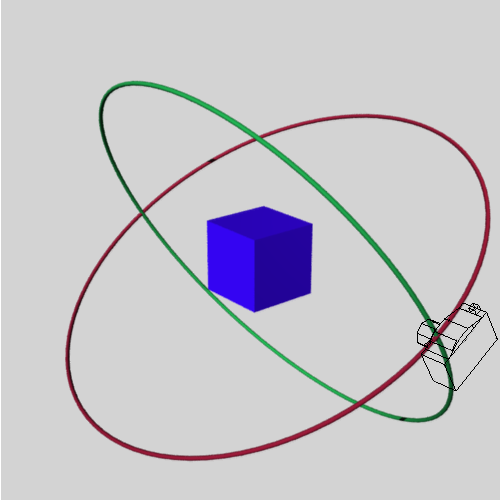
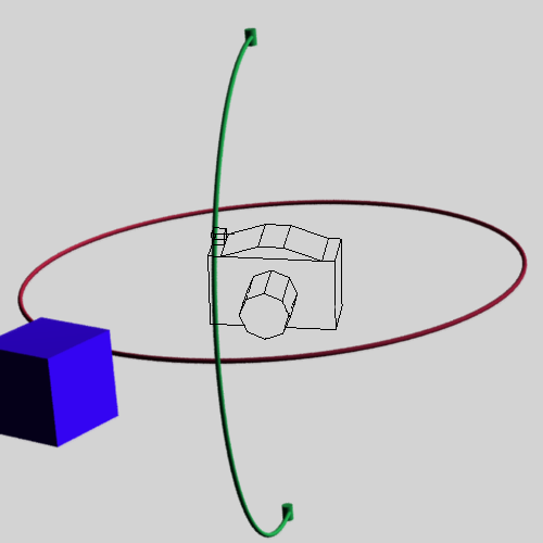
|
In the second image, the viewpoint has been moved up. Notice that the view camera is still pointing directly at the rotation center. Left & Right pan are along a plane perpendicular to the Y-axis. |
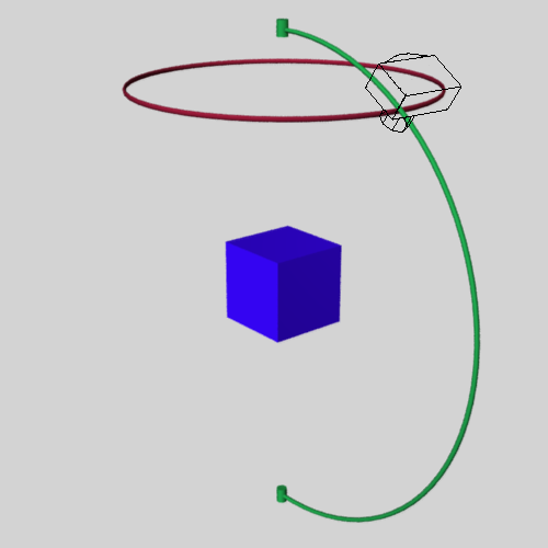
Note
The green path always ends at points directly above and below the rotation center, reckoned along the Y-axis.
Note
The viewpoint cannot “Barrel roll” in this mode. The upper endpoint of the green path will always be straight “up” in the view
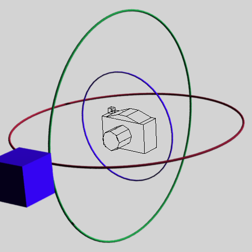
13.2.2.3. Space or Gimbaled Sphere
This mode is a little less constrained than Tray mode. It also rotates around a selected center point. Choosing this center points works exacly like tray mode.
Zoom/Z-axis Likewise works the same as Tray mode.
Tip
It’s a little bit easier to lose track of your orientation when using space mode. If this happens, you can change the mode back to Tray temporarily. The view will be turned right-side-up, while still pointing at the same location.
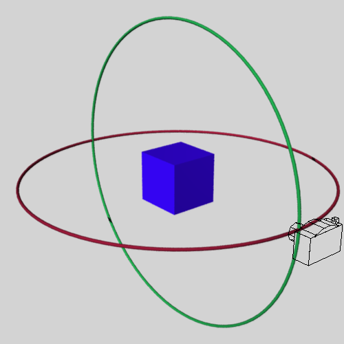
|
|
|
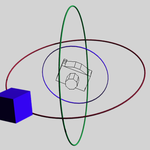
Rotation in the vertical path does not have stopping points. |
Left & Right rotation are relative to the current view direction. |
Space mode can barrel roll! (see the mouse control table.) Up & Down rotation are relative to the current view direction. |
13.2.2.4. Fly “Boom”
This mode allows you to maneuver in three dimensions throughout the scene. Rotation takes place around the viewpoint itself - think of turning your head to look to the side and up or down.
Zoom/Z-Axis movement happens along the view direction. (But See Scroll-Cues - it’s a little more sophisticated than that)
|
Left and Right pan are relative to the current view direction |
|
Fly mode can Barrel roll! Pan directions are also relative to the current roll angle. |
13.2.2.5. Drive or Dolly
This mode is a slightly more flexable version of an old-school camera dolly. The viewpoint can rotate up and down, and to the left and right along a plane perpendicular to the Y-Axis.
Zoom/Z-Axis movement happens along a plane perpendicular to the Y-Axis in the view direction - think of looking up at the ceiling, then take a step forward. (See also Scroll-Cues for some of the more advanced things you can do here)
|
Left and Right pan are around the camera Y-Axis. Up and Down pan are stopped at vertical. |
|
Left and Right pan are still around the Y-Axis, even when the camera is tilted up or down. |
13.2.3. Zoom-Control Cue Graphics
When the view control mode is one of the travel modes, (Drive or Fly) using the zoom control has a more complex effect. If the mouse cursor is at the center of the view, the zoom behaves as described in the applicable section above. Away from the center of the view, some additional features come into play.
To guide you in the use of these features, the AOI interface supplies optional visual guides, called scroll cues. These can be enabled or disabled through the Edit → Preferences Menu.
The options for when to show the cues are:
- Never
Uncheck the boxes
- While Scrolling
Bring up the cue when the mouse zoom function is active
- On Idle
Always on if the view is in an appropriate mode
Note
The effects that these cues describe are always on! The preferences only control whether to display “sighting targets” to make using them a little bit easier.
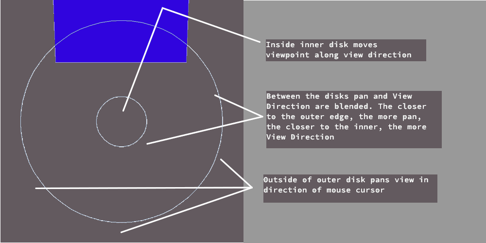
For Fly mode, the cue is a pair of concentric circles:
For Drive mode, the cue is a pair of nested squares. The various zones are also a little more complicated than in Fly mode.
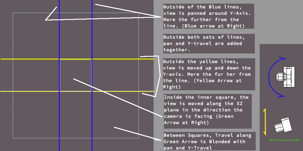
The vertical and horizontal lines are for illustration only - the actual cue graphic only conists of the nested squares.
13.2.4. View Frustrum Cue
Optionally, AOI can display cues that help verify the location and orientation of the viewpoint one is moving. This only works in the 4 viewport configuration.
This cue can be enabled or disabled through Edit → Preferences You can set the cue to be displayed for any active view, or only camera views.
The color of the frustrum is significant: If light blue, you are seeing it from the “outside” - as if you are looking over the shoulder of the represented viewpoint. If it is orange, you are looking at it from the “inside” - looking back toward the viewpoint.
13.2.4.1. Perspective Frustrum
If the view that is being moved is Perspective Projection, it’s frustrum will display as a four sided pyramid, with the tip at the viewpoint.
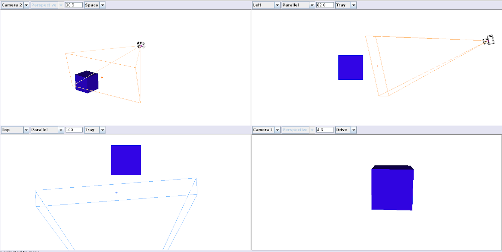
In this shot, the lower-right Viewport, set to ‘Camera 1’ is being moved.
Note that the size and shape of the base of the pyramid represent the field of view that is shown in the ‘Camera 1’ viewport, but the camera itself looks off to infinity within that field of view.
13.2.4.2. Parallel Frustrum
If the view that is being moved is Parallel Projection, it is it is represented by a rectangular plane.
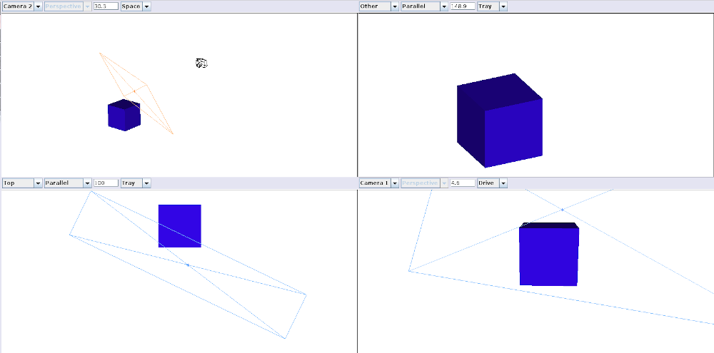
In this shot, the upper-right viewport is being moved.
The rectangle represents the exact dimensions of the viewport, as if it was embeded in the scene like a sheet of glass.
13.2.5. Rotation Indicator Dial
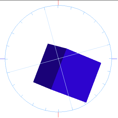
One last cue can be enabled: If you enable ‘Show tilt dial’ you will get visual feedback on how far you have rotated the view when performing a barrel roll.
In the image, the view has been rolled approximately 15 ° counter-clockwise
Note
The indicator shows the relative rotation from when you began this roll. If you release the mouse, it will reset, and the next roll will start at 0 °