5. Lights
Lighting in a scene is very important to create the right atmosphere and mood, from the serene to the dramatic. It is beyond the scope of this manual to discuss how to create these moods so I shall stick with explaining the lighting modes possible in Art of Illusion and introduce a few special effects and leave you to experiment further.
There are 3 types of light in Art of Illusion: point, directional and spot. There also are variations on these whose properties are defined by a procedure.
5.1. Point Lights
This type of light emits light equally in all directions. Point lights are created either by clicking on the light icon
![]() and then clicking on the view window to define its position, or by selecting Object -> Create
Primitive -> Point Light which brings up a layout dialogue box allowing its position and orientation to be accurately
specified. Scaling has no effect on light objects.
and then clicking on the view window to define its position, or by selecting Object -> Create
Primitive -> Point Light which brings up a layout dialogue box allowing its position and orientation to be accurately
specified. Scaling has no effect on light objects.
On the view windows, the point light looks like this:

Having created the point light, it can be edited either by double-clicking on it in the Object List or by selecting it and clicking on Edit -> Edit Object.
The point light dialogue box is shown below:
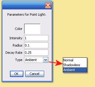
Click on the Color box the alter the light’s colour. This brings up a dialogue allowing Hue/Saturation/Value (HSV), Red/Green/Blue (RGB) or Hue/Lightness/Saturation (HLS) values to be set to define the light colour.
The Intensity, I0, of the light is simply how bright it is. By default, this set to 1. The intensity of this light at any point in space, I(r), is a function of this value, the Decay Rate, d, and the distance from the light source, r as follows:
I(r) = I0/(1+dr+(dr)2)
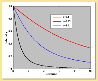
Close to the light (r<<1/d) the intensity is approximately constant. Far from the light (r>>1/d), it follows an inverse square law (i.e. decays as 1/r^2) as shown in the plot below for a range of decay rates:
The Intensity of a light source can be negative. In this case, it becomes a source of ‘darkness’ which, although physically unrealistic, can be a useful effect.
The Decay Rate defines the drop off in the intensity of the light per unit distance from the light. A high value means that the light will be bright only very near to the light source, while a small value means it only drops off a little. A value of 0 causes the light to be the same brightness everywhere.
The Radius defines the physical size of the light. This only has an effect if Soft Shadows are switched on when rendering with the Raytracer. Increasing the radius has the effect of making shadows softer at their edges.
The Type can be Ambient, Shadowless or Normal. Normal means the light behaves realistically, Ambient means the light comes from all directions and equally illuminates all surfaces in a volume, Shadowless means that the light illuminates surfaces as expected but does not cast any shadows. The image below shows the difference for light with the same intensity and decay rate:
5.2. Directional Lights
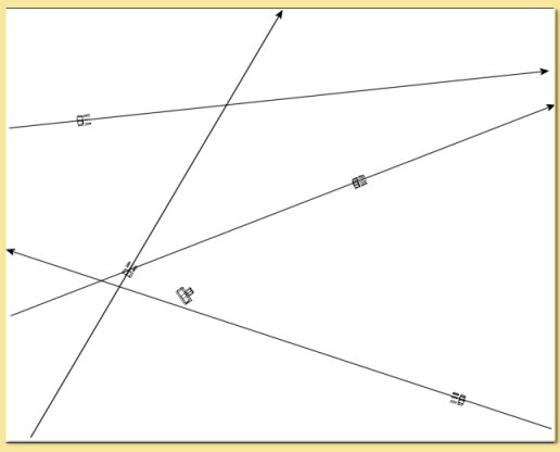
Directional lights are infinitely-wide beams of parallel light, i.e. the light emitted by them travels in one direction only. The direction is defined by the light’s orientation. It is important to note that the light travels in this direction from a point infinitely far away and not from the position of the light source as illustrated in the figure below. Because they are infinitely wide, any of the light sources shown on the diagram could have been positioned at any point in space and still have had the same effect; it is only their orientation that matters.
Directional lights are useful for simulating light sources which are far away, the most obvious example being the sun. Light from the sun is virtually parallel because of the tiny angle subtended even across the whole Earth’s diameter. Also intensity does not drop off over noticeably as the Earth’s diameter is small compared with the distance the light has already travelled.
To create a directional light, either click on the light icon and then click its position on a viewport and drag in the required direction (if you do not drag, you will end up with a point light), or select Object -> Create Primitive -> Directional Light and enter the position and orientation as prompted.
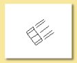
Directional lights are represented by this symbol in the view windows with the light beams indicating the direction of the beam:
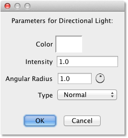
Because of their inherent simplicity, the editing dialogue box brought up by double-clicking the light on the Object List or via the Edit menu, allows only 2 parameters to be specified:
Color - allows the light’s colour to be specified with the usual 3 HSV/RGB/HLS bars.
Intensity - allows the brightness to be specified. This value is independent of position.
Angular Radius defines the physical size of the light. This only has an effect if Soft Shadows are switched on when rendering with the Raytracer. Increasing the angular radius has the effect of making shadows softer at their edges.
Type is as defined above for point lights.
5.3. SpotLights
Spotlights produce a cone of light. They are created by selecting Object -> Create Primitive -> Spot Light and then defining position and orientation.
Spotlights look like this when displayed in the view windows:

This clearly shows the orientation of the emitted light beam.
Once created, spotlights can be edited either by double-clicking on the light in the Object List or be selecting the object and clicking on Edit -> Edit Object. This brings up a dialogue box like this:
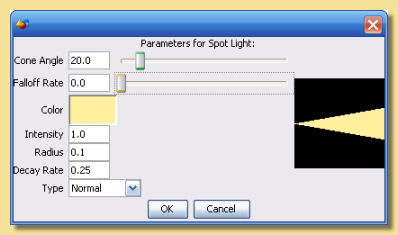
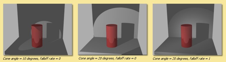
Cone angle is the extent of the beam spread. A small value produces a narrow beam.
Falloff rate defines how quickly the light fades as we move radially outwards from the centre of the beam. A value of 0 means there is no falloff and the light will therefore be of uniform intensity right to the edge of the beam beyond which it will be zero.
Radius is the physical size of the light which affects rendering with soft shadows switched on (see Rendering).
Color, Intensity, Decay Rate and Type are as defined for Point Lights.
The examples below show the effects of varying the cone angle and falloff rate:
AIMING SPOTLIGHTS
Often it is useful to have the ability to aim spotlights accurately in order to illuminate a particular part of the scene. Below are 2 helpful hints to allow this:
1. Using a SpotCam
Create your spotlight via Object -> Create Primitive -> Spotlight and accept the defaults. Now create a camera and accept the defaults too. Both objects will be at the same position and have the same orientation. Make the camera (‘Spotcam’) a child of the spotlight by dragging it up under the spotlight in the Object List (see here for more details) - now wherever you drag and point the spotlight, the camera will follow. So, in order to see where the spotlight is pointing, change one of the view windows to show the Spotcam. Now rotate and drag your spotlight - the Spotcam view shows what the spotlight is illuminating - simply rotate the spotlight until the part of the scene is visible in the Spotcam view - your spotlight is now pointing in the right direction.
2. Using a Constraint Track
Animation tracks have uses beyond just animation and here is one example. Using this method, we will be able to get the spotlight to point towards a particular object.
Create the spotlight in the normal way. Click on Animation -> Show Score, select the spotlight and go to Animation -> Add Track to Selected Objects -> Constraint. Move your spotlight to where you want it positioned. Now create a Null object which will be the target for the spotlight to aim at. Move the Null to the appropriate position in the scene. Now select the spotlight and double-click on the Constraint track on the score. In the dialogue that appears set the Orientation to ‘Z Axis’ and the box to the right of it to ‘Faces Toward’. Then click on the ‘Set:’ button underneath and select the Null object from the list that appears. Click ‘OK’ and ‘OK’ again to leave the dialogue and return to the scene. Your spotlight should now point towards the Null. Now all you have to do to point the light is to move the Null to wherever you want to light to face - note that the spotlight doesn’t update in realtime when you move the null - you need to advance the score to effect the change.
5.4. Procedural Lights
The lights described above are defined by simple physical properties: their color, their brightness, etc. Sometimes you want something fancier. What about a light that gives out different colors in different directions? Or one that projects a picture onto a wall? Or a light that produces bright and dark bands at different distances from the light source? You can do all of these with procedural lights.
To create a procedural light, select Object -> Create Primitive -> Procedural Point Light or Object -> Create Primitive -> Procedural Directional Light. The difference between the two is what direction the light rays travel in. For a point light, they travel outward from the location of the light. For a directional light, they are all parallel to each other.
Having created the light, it can be edited either by double-clicking on it in the Object List or by selecting it and clicking on Edit -> Edit Object. The window that appears will look something like this:
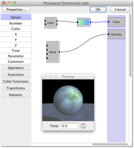
This is a procedure editor. The ‘Color’ and ‘Intensity’ boxes on the right are the properties of the light at a point in space: its color and its intensity. You get to define exactly how those properties should be calculated. You do this by creating a mathematical procedure that takes the x, y, and z coordinates of a point in space (defined in the light object’s local coordinate system), and computes the color and intensity at that point. See the section on procedural textures to learn how to create procedures.
Click the Properties… button to edit the light’s other properties: its radius (for a point light) or angular radius (for a directional light) and type. These have exactly the same meaning as for regular point and directional lights.
For ordinary directional lights, it doesn’t matter where you put the light in the scene, because it produces the same light everywhere. That isn’t necessarily true for procedural directional lights: you can create a procedure that makes the light color and intensity vary with position. In that case, it does matter where you put the light.
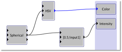
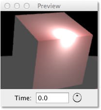
There are no “procedural spot lights”, because you don’t need them. Just use a procedural point light, then create a procedure that makes its brightness vary with angle:
Procedural lights are especially useful for creating ‘non-physical’ lighting effects that could never be created by real lights. This isn’t realistic, of course, but it can be very useful for artistic effect.
Be careful when using procedural lights with photon mapping (described here). Photon mapping assumes a physically accurate lighting model. If you use it with a non-realistic procedural light, the results can be unpredictable and usually are not what you want.
5.5. Lighting Effects
3.5.1 Realistic Light Sources
Like most, if not all, 3D graphics packages, the light sources in Art of Illusion are themselves not actually visible. If you point the camera at a light source and render the view, there will not be a bright area where the light source is. Lights are only visible in the way they interact with objects around them. In most cases, this is useful as lights can be positioned anywhere in the scene without having to worry about them being visible as is the case in real life.
Sometimes, however, it is desirable to replicate real life sources. To simulate a realistic light source requires 2 qualities: (i) the object needs to give out light that reacts realistically with its surroundings and (ii) the object needs to ‘glow’. In real life, these qualities are manifestations of the same physical feature but they are quite different in 3D graphics.
The first thing to do is to create the object you want to represent the light source. The image below is an example of a ‘bulb’ which was created by applying the lathe tool to a curve. The rendered image shows the bulb ‘turned off’.
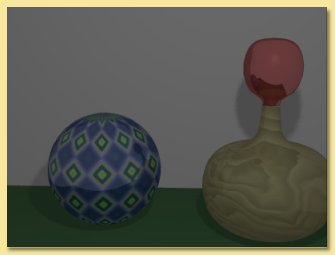
To make it into a light source, we need to put a light source inside it. The point light source is the best type for this purpose. Having positioned the light in the bulb, you will need to make the bulb transparent so that the light can escape and, thus, interact with its surroundings. Alter the transparency in the texture to achieve this.
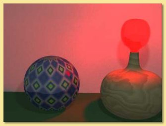
The light will now shine out from the object but the object itself will not ‘glow’ and so will not look realistic. To get this effect, add some emissive colour to the object. Alter the diffuse and emissive colours to get the right effect and make sure the overall colour matches that from the light. The image on the right shows the results of these changes.
Note that ‘soft shadows’ had to be switched on otherwise artefacts can appear when light sources are placed inside objects.
Another example of ‘realistic’ lighting is shown on the right. The ‘lights’ are cylinders with point light sources positioned within:
If you’re rendering with Global Illumination (GI), there is another option; that is to use an emissive textured object to produce the light. With GI, emissive textures actually give out light and this may be suitable to avoid having to use transparent objects/light sources. See here for more details.
Although directional lights are simple, they are ideal for use in more advanced lighting techniques. For example, a cucaloris or ‘cookie’ (a sheet of card with holes cut in it) can be used to create artificial light arising from off-screen objects. In the example below, a ‘cookie’ was made in a graphics program as a simple binary image. When this is used as a transparency image map (See Textures and Materials) in the set up below, only the cut-out shapes allow the light to pass through. This sort of effect has been used in CGI movies for things like leaf-dappled forests. The parallel quality of directional lights means that the image shapes are preserved.
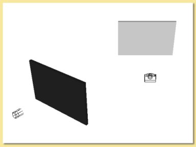
Perspective view of set up for ‘cookie’ scene. The screen on the left has the cookie image set for a transparency map and is projected onto right hand screen at which camera is pointing.
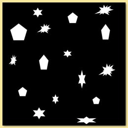
Binary image map created in 2D graphics program.
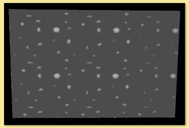
Resulting image. Could be used for leaf-dappled shadows etc.
The binary cookie image could be replaced by an transparent imagemap to give a ‘slide’ projection.
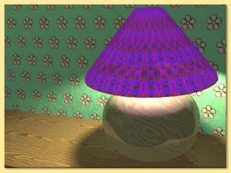
Collimation of light sources can also be used to good effect either using geometric objects or through the use of textures. The image below uses the lamp shade object to effectively collimate the light source within it to simulate the lighting from a lamp.
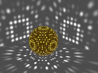
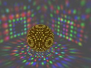
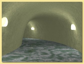
The images below were made by putting light sources into a sphere which was assigned a procedural texture that made small circular areas transparent. The left image has one white light source inside the sphere, whereas the right hand image has 3 light sources at slightly different positions; red, green and blue. All images below were rendered with ‘soft shadows’ on (see Rendering).